

How To Make A Computer In Minecraft
![]()
![]()
This article aims to examine the pattern and implementation of redstone computers in Minecraft. This Article is extremely complicated, for nerds.
See Affiliate ane, Tutorial on Building a Computer, for a detailed tutorial on edifice a estimator in Minecraft and how to aggrandize and amend on the example. Does non require whatsoever extensive noesis of calculator science. NOT FINISHED.
See Affiliate ii, Planning a Redstone Computer, for basic computer concepts of designing and understanding a redstone computer in Minecraft. Does non crave any extensive cognition of informatics.
Contents
- 1 Overview
- ane.ane Implementations
- 2 Chapter 1: Tutorial on Edifice a Computer
- 2.ane Introduction & Prerequisites
- ii.2 The MASIC Calculator
- 2.3 Stride 1: Memory and Accost Decoders (THEORY)
- 2.4 Step 1: Memory and Address Decoders (Exercise)
- 2.four.1 Address Decoder
- 2.5 Footstep 2: Edifice an Arithmetics Logic Unit of measurement (THEORY)
- ii.v.1 Adding ii numbers
- 2.five.1.ane Partial numbers
- 2.5.2 Subtracting two numbers
- ii.5.3 Multiplying two numbers
- ii.v.1 Adding ii numbers
- ii.6 Footstep 2: Building an Arithmetic Logic Unit (Do)
- 2.7 Step 3: Teaching set and car compages (THEORY)
- ii.7.one Prerequisites
- 2.7.ii The MASIC Instruction Set
- two.seven.three Writing programs
- 2.7.4 Instruction Bicycle
- 2.8 Step 3: Instruction gear up and machine architecture (PRACTICE)
- 3 Chapter 2: Planning a Redstone Estimator
- iii.1 Fundamentals of a Computer
- 3.2 Auto-Architecture
- 3.3 Computer Data Storage
- 3.3.1 Chief Storage
- 3.iii.1.ane Registers & Flags
- three.3.two Caches
- three.three.iii Random Access Retention (RAM)
- 3.3.4 Secondary Storage
- three.3.five Tertiary Storage
- 3.3.1 Chief Storage
- 3.four Execution Model
- iii.4.1 Harvard
- 3.four.2 von Neumann
- three.v Word sizes
- iii.five.ane Data-Discussion
- 3.5.2 Instruction-Give-and-take
- three.6 Instruction Set
- 3.vii Architecture of the Computer
- 3.7.i Busses
- 3.vii.two Components
- four Tips
- v See likewise
- six References
Overview [ ]
Computers facilitate the implementation of ideas that are communicated from humans through programming.
This article volition explain the nuts of designing and edifice a computer in Minecraft, bold the reader is fairly familiar with redstone and computers to a basic level.
There really is no way of building a estimator without knowing how a computer works. The tutorial attempts to explain everything that y'all need to know but does require a bit of understand here and there of computer science, which is stated in the prerequisites section of each tab. The deepest part nosotros cover is up to IGCSE CS.
All figurer systems have at least one processing unit. During operation, processing units execute instructions stored in the figurer's memory. For a adept start on Minecraft computers y'all should learn computer science. There are many sources and tutorials to larn computer science only for a basic start, it is recommended to sentry Crash Course on Computer Science particularly episodes 1–eight. Although it isn't completely thorough, it can work equally a basis in your understanding of computers.
Most computers in Minecraft are made of redstone dust, redstone torches, and repeaters, leading into sticky pistons or redstone lamps which are controlled using a series of buttons, levers, pressure level plates, etc. Other proposed ideas (non covered) are to use hoppers, mine carts, or boats with redstone.
See chapter 1, Tutorial on Building a Reckoner, for a detailed tutorial on building a computer in Minecraft and how to expand and improve on the given example. It does not require any all-encompassing cognition of Informatics equally information technology volition be explained but will delve quite deep into it.
See chapter 2, Planning a Redstone Estimator, for basic figurer concepts of designing and agreement a redstone computer in Minecraft. It does non crave any extensive noesis of Estimator Science only will delve quite deep into it.
Implementations [ ]
Computers tin be used in many ways, from creating a smart house to using information technology to run an adventure map. However, due to the limitations of computers in Minecraft, stated below, they remain an abstruse concept and serve as good tools to sympathize lower-level concepts of CPU architecture and embedded systems.
The matter that sets apart computers and calculators are that calculators cannot perform multiple instructions in a row without user input. A reckoner can compare and assess instructions in a flow to perform tasks.
However, in Minecraft, they are extremely tiresome and with their large size, redstone computers are hard to find practical applications for. Even the fastest redstone computers take seconds to complete one calculation and take up a few thousand blocks of space. Command blocks are far superior to computers in Minecraft considering of their speed and legible, higher-level commands.
Mods can modify the computer's speed such as TickrateChanger will change the tick charge per unit of the game.
Chapter 1: Tutorial on Building a Computer [ ]
Introduction & Prerequisites [ ]
Redstone logic closely reflects simple binary logic, as redstone tin can exist either on or off, and tin, therefore, be interpreted as 1s or 0s. We volition be referencing in this tutorial, bones binary logic and various elementary reckoner scientific discipline terms. There is an excellent commodity which explains binary and conversion to binary. Please read the Compages of building the Computer section every bit we will be following that to programme our computer, it is located in this article, cheers.
This chapter volition focus on the application of the knowledge and manipulation of redstone to create a uncomplicated 8-bit computer, and will draw how to make one and how information technology works.
All subjects volition be split into (THEORY) and (Do), THEORY will get in-depth of exactly what volition go on. PRACTICE will cover how to build it in Minecraft, what it will await like and mayhap world downloads.
The computer we will be building (MASIC Computer)
Footstep one: Memory and Accost Decoders (THEORY) (NOT FINISHED)
Step 1: Retentivity and Address Decoders (PRACTICE)
Step ii: Building an Arithmetic Logic Unit (THEORY)
Step 2: Building an Arithmetic Logic Unit (Exercise) (Non FINISHED)
Stride 3: Teaching set and car architecture (THEORY)
Step iii: Teaching ready and machine architecture (PRACTICE) (NOT FINISHED)
There are three primary design objectives for a estimator in Minecraft, to make your reckoner most suitable for your task at paw. In that location are trade offs to consider, such as the larger the computer, the slower it will get considering the number of redstone repeaters will increment by distance. The more retentiveness, the less speed and larger size.
- Compactness
How pocket-sized is the computer? In Minecraft, designing a survival calculator volition virtually likely emphasize on this point. The number of repeats required volition increase as size increases.
- Memory
How much retentivity tin can it hold? How many bits and numbers tin can information technology count up to? This is important for large-scale computers, say ones which can practise more circuitous algorithms and crave larger instruction sets (e.g. doing square roots or trigonometry). The larger the memory size or bit architecture, the more than complex the computer will get.
- Speed/Performance
How fast tin can it do operations? Is it optimized to run its tasks? Custom designing and building a computer will significantly increment its speed every bit more than redundant wiring and lawmaking could be switched to purpose-built hardware and software. This is apparent in some real-globe supercomputers which are programmed to run i chore very, very efficiently. The speed of computers in Minecraft is very slow, therefore a mod could be installed for the client to significantly increase the speed of the game, and therefore the computer.
The MASIC Calculator [ ]
The work in progress figurer which we will be making in the tutorial. eight bits, sixteen bytes of RAM. I/O is a seven-segment display (for hex and decimal) and a control console which nosotros will make.

The MASIC computer aims to be a 1-size-fits-all computer and does not specialize in one task, then it is fully programmable by reading its ain memory (explained in Section two: educational activity sets). The unproblematic I/O is great for multipurpose employ and the retentiveness is sufficiently sized. It runs at quite a fast speed (because of its small size).
Pace ane: Retentiveness and Accost Decoders (THEORY) [ ]
Decoders convert binary figures into decimals. For example, looking at the viii-bit decoder, 00 turns on the get-go lamp which stands for 0. 01 turns on the 2nd lamp which is one. 10 turns on the third which is 2. eleven turns on the final one which is 3.
Step 1: Retentivity and Address Decoders (PRACTICE) [ ]
Accost Decoder [ ]
0000 0000 (notice output 1 is lit)
0000 0001 (notice 2nd output is lit)
0000 0010

0000 0011
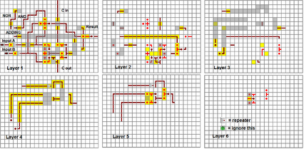
This is the pattern for the address decoder nosotros are going to build.
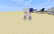
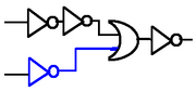
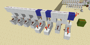
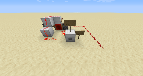
Above is a simple two-bit land, so it has two inputs (left and correct) through the repeaters. The output is the redstone line higher up which will turn OFF when the state is met. The state is whether the redstone input volition plough OFF the redstone line above; if so, the state is the redstone inputs. In the in a higher place case, the left must exist turned OFF (0) and the right (blue) must be turned ON (ane) to yield an OFF on the summit redstone line. So it expects a country of OFF ON (aka 01 for binary).
They are colored bluish for bits which should exist ON (1) for it to stop powering the peak redstone line. Once equally stops powering the redstone line, information technology and so turns off.
These are basically either one or two NOT gates feeding into a OR gate and and then NOT the output.
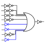
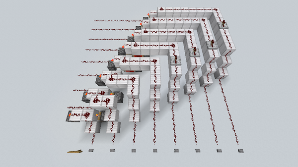
Above is an eight-bit state, it expects 8 inputs in exactly the order 0000 1101. And so that country it expects is 0000 1101. And then the redstone torches power the inputs, and so nosotros run into the redstone line on the acme turns OFF (only when exactly three redstone torches are placed in that exact gild of 0000 1101).
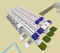
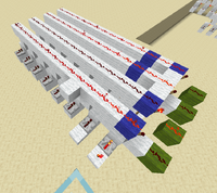
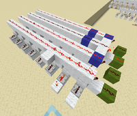
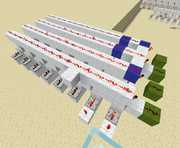
Now if we put multiple of these together, we can count up in binary with the blue bits to go all 255 states of 8 $.25. The one below is 8 bits, and has four country expectations. See the correct images to run across information technology in action. Now each dark-green output can be a memory cell, and if nosotros continue counting in binary, it will reach 255.
The input is 0000 0011 (see the redstone torches for input) and where the blueish bits match the current land, the green output is ON.
- 0000 0000 - first signal out (on the images on the correct)
- 0000 0001 - 2nd signal out
- 0000 0010 - 3rd signal out
- 0000 0011 - fourth signal out
So at present nosotros keep counting upward in binary to become up to 0000 1111 and end there; nosotros should at present accept 24 (16) state expectors. At present we're done with the address decoder. Nosotros do not go on counting up to 1111 1111 because of instruction gear up limitations, explained in section 3: instruction sets
Step 2: Building an Arithmetic Logic Unit (THEORY) [ ]
The Arithmetic Logic Unit referred to equally the ALU volition compare and perform mathematical operations with binary numbers and communicate the results with the Control Unit, the central component of the computer (and Central Processing Unit but that is going to be as large equally the computer itself). Many tutorials will want the reader to build an ALU start, and therefore the topic is covered very widely effectually the internet.
The ALU nosotros will be edifice can perform iv important operations on ii inputs and return a correct output. A, B, being both 8-fleck inputs
- A + B (Add A to B)
- A >> (bitshift A right (the aforementioned equally binary split up by ii))
- << A (bitshift A left (the same every bit binary multiply by two))
- Not A (The opposite of A)
At that place can as well be multiple ALUs inside a computer, as some programs require a lot of operations to run, which practise non depend on the previous operations (so they can be threaded) so delegating them to different ALUs could significantly speed up the program.
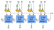
binary adder
Adding 2 numbers [ ]
In an adding unit, for each flake (for our computer, we require iv, hence four-bit), there is a full adder. The total adder will accept three inputs, each input tin be either 1 or 0. The first two will exist the user'due south input and the tertiary will be the deport input. The bear input is the output of the previous full adder, this volition be explained afterward. The adder will output 2 statements: first, the output so the comport output, which is sent every bit input into the side by side full adder, a place value upwardly. For instance, I wish to add the number 0101 to 1011. The first full adder will consider the first place value, 1 and one as their two inputs (we are reading correct to left). At that place is no carry input as there is no previous full adder. The full adder volition add 1 and 1; which is 0, and carries a 1 to the next place value. The adjacent full adder would add 0 and 1 and the carry input would be 1 which the previous full adder stated. The output of 0 and 1 would exist 1 but there is a behave input of 1 and therefore volition add 0 and 1 and 1, which is 0 and carries a i to the next place value. Reviewing add-on in binary should resolve any confusion.
All ALUs, to perform adding operations, require the presence of multiple adders. Every two bits will feed into an adder which, when joined with other adders, volition produce an output which is the sum of the two bytes added together. An adder has an input, an output, and two carry input/output every bit would a person bear when doing the addition of 9 + i or 01 + 01. The adders are made of logic gates which is possible by the classification of binary. Tutorials/Arithmetic logic gives a very detailed look into total adders and half adders, for now, at that place is a schematic of how to construct one. It gives four inputs/outputs and should be connected with other adders to create a unit. For this example, nosotros volition connect four adders together in our four-bit estimator and so that we can take in all 4 bits to make an output. There will exist an input carry missing from the kickoff adder, this is because there is nothing to bear from the bit earlier it, information technology is the first fleck. The input conduct will remain at nil. There volition likewise be an output bear missing from the fourth adder, and the output of this will be ignored equally we can just support iv bits. The boosted fourth acquit output is wired to the overflow flag to signify the performance couldn't be done. This is called a binary overflow.
So basically, go into Minecraft and build a full binary adder (picture) and connect them up. There should be eight inputs and outputs. Try placing levers and redstone lamps at the respective ends to exam your creation. And so 0010 + 0011 should yield 0101 (two + 3 = 5, we are reading right not left).
Partial numbers [ ]
A reckoner takes intendance of numbers less than i past class of float-point arithmetic, it is but so useful in larger-fleck computers (xvi-64 $.25) and computers which practise need to use numbers less than ane. Floating-signal arithmetic or arbitrary-precision arithmetics are ii ways to achieve this. Another simpler but less efficient way would be to assign all numbers a power of two so that they are 'bumped up' by the power of two called. The player must do this to every number and assume the one as one times the power of the two you lot have called. For case, 5 = 1012 so 5 × ii3 = 101000two; five is bumped upwardly by three. So now, ane in your new system would be 1 × 2iii = m2 and that would leave room for 0.1, 0.01 or 0.001; 0.01 * 23 = 102. This leads to a more complicated setup for your calculator.
Subtracting ii numbers [ ]
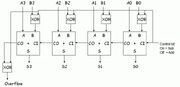
An adder with all labeled parts.
The subtraction of numbers is surprisingly simple. The ALU start must change the 2d number (the value subtracting by) and convert it from a positive number to a negative number. A two's complement is when you invert the binary number (then that all the 0s are 1s and 1s are 0s) and add together one to information technology.
Example: do 10 subtract ix
| one. 0000 1001 | (9 in binary, we want -9, not 9) |
| 2. 1111 0110 | (Invert nine, then that all 0s are 1s and 1s are 0s) |
| 3. 1111 0111 | add together one (this the two's complement of 9) |
| iv. | |
| 0000 1010 | (x in binary) |
| +1111 0111 | add two'due south complement of 9 (aka -nine) |
| ---- | |
| 0000 0001 | issue (10 + (-9) = i) (in that location is an overflow, this just means that the result is not a negative number) |
This poses the complexity of signed numbers.[1] This is a weight to the binary number to assign it as a positive or negative number. Whether the upshot is a negative or positive number is determined by the overflow flag. If there is an overflow, this means that the number is positive and otherwise, negative.
To implement this, you can ask the ALU to practice 3 operations. To do A subtract B, the operations are
Operation: A SUB B
- Non B
- (set up B to) B ADD 1
- (set A to) A ADD B
- RETURN A
Multiplying two numbers [ ]
Multiplication is repeated addition, so the easiest (inefficiently) is to add A to a variable B amount of times.
Here'due south pseudomachine lawmaking for it
Operation: A * B
- C = 0
- (set C to) C ADD A
- (set B to) B SUB 1
- JUMP IF (B > 0) TO LINE 2
- Return C
Even so, at that place are more efficient ways of multiplication. A proficient method is to repeatedly bitshift the offset number to the location of each one in the second number and sum information technology.
There are underscores to mark indents, since padding with 0s are less intuitive. subscript 2 means in binary, and decimal numbers are also in bold
| __ __11 | 3 (find that there are ii 1s) |
| x_ 1011 | 11 |
| ---- | |
| __ __11 | Nosotros shift xiii by 010 since the 1st bit of 1011ii is one2 |
| +_ _110 | Nosotros shift 112 by one10 since the 2nd bit of 10112 is a 12 |
| +ane 1000 | We shift 112 by 310 since the 4th bit of 10112 is a i2 |
| ---- | the 3rd chip of 10112 is 02 so we do not add a 112 there |
| x 0001 | 33 (upshot) |
and then this is more efficient for larger numbers.
Operation: A * B
- C = 0
- D = 0
- (Ready A to) << A (bitshift A to the left)
- JUMP IF (BIT (D) OF B == 0) TO LINE six
- (Set C to) C Add together A
- (Ready D to) D Add together 1
- JUMP IF (D < LENGTH OF B) TO LINE 3
- Render C
Don't forget that
<< A (bitshift to the left) is effectively, A * 2
and
>> A (bitshift to the right) is effectively, A / ii
If the numbers are predictable or the CPU must do a lot of like numbers in bulk, consider using a wait-upwards table to quickly get results to frequently chosen multiplication. Is this a way of hard-coding your answers and is used in extreme cases.
Step 2: Building an Arithmetic Logic Unit of measurement (PRACTICE) [ ]
Stride 3: Instruction set and machine compages (THEORY) [ ]
This is pretty fun, this part.
Elaborating on Chapter two: Instruction Ready, we will be creating 1 for ours.
For the MASIC Computer, the computer which nosotros are building, has an 8-bit organization, so that means each instruction on each slot of the stack retentivity will be 8 bits. The stack memory is the memory where any data can exist stored and is on the RAM. In that location will be a counter, called the program counter, which increments by 1 every cycle. A cycle is the CPU fetching the instruction, decoding the instruction (finding out what to do with the instruction) and executing the teaching (doing what it tells it to do). So information technology moves on to the adjacent one by incrementing the program counter and reading the data at that location in the stack retentiveness.
Then each byte in the stack memory has viii bits for the states to work with.
0000 0000
and some instructions require an address, say loading memory into a register so that we can perform operations (such as addition) on information technology. Each instruction will be split into 2 parts, each four bits. The first is the TYPE. the Type will specify what the computer must practice and the ADDRESS volition be where the value we will perform our operations are located.
OPCODE OPERAND
then 4 $.25 for the TYPE, we can take ii^four types, so sixteen different ones. Our figurer will accept ii registers, so one bit will be for specifying the register the operation will executing on and is denoted past an x.
Instructions are put in the same identify as memory and every bit the ADDRESS office of the education is only four bits, we can only reference memory from 1-sixteen lines, requiring some clever programming to fit larger programs. Memory is besides limited to 16 bytes per program. Values and instructions are substantially the aforementioned affair, so if you write an instruction to shop it onto a line that previously-stored an instruction, that effectively overwrites the instruction with a value. Accidental execution of values might be a trouble, then a Terminate command must be used to prevent any errors. This is a whole lot to understand, so good sources are https://www.computerscience.gcse.guru/theory/loftier-depression-level-languages and https://scratch.mit.edu/projects/881462/ <-- really helpful actually. and also don't forget to take both CS and ICT for your IGCSEs.
Prerequisites [ ]
The department will cover simple topics and components unremarkably found in a figurer, and so information from chapter 2 will be used, such every bit the ALU, RAM, registers and binary manipulation.
The MASIC Education Set up [ ]
Since the reckoner Here is the first draft of the instruction set, with simply essentials. This is based on other associates languages, merely changed to adapt to our architecture. There are two registers, so we need instructions to perform operations on both registers.
| BINARY | OPCODE | Comment |
|---|---|---|
| 0000 | LOAD R1 | Load the Accost into register 1 |
| 0001 | Store R1 | Store contents of register 1 into Accost |
| 0010 | Jump R1 IF | Jump to line ADDRESS if register ane is equal to 0 |
| 0011 | ADD R1 | Add together contents at ADDRESS to annals i |
| 0100 | <<R1 | Bitshift register i left |
| 0101 | Non R1 | Bitwise NOT annals 1 |
| 0110 | Bound | Jump to line OPERAND |
| 0111 | Cease | Terminate the program. |
| one thousand | LOAD R2 | Load the Accost into register 2 |
| 1001 | Store R2 | Store contents of register 2 into Accost |
| 1010 | JUMP R2 IF | Spring to line ADDRESS if register 2 is equal to 0 |
| 1011 | ADD R2 | Add Accost to annals 2 |
| 1100 | <<R2 | Bitshift register ii left |
| 1101 | NOT R2 | Bitwise NOT annals two |
| 1110 | OUT R1 | Outputs register 1 |
| 1111 |
To translate:
1000 0011 means LOAD R2 iii considering LOADR2 is 1000 and 0011 is 3.
These can be in a procedure then that functions can be performed.
Writing programs [ ]
This one does the Fibonacci sequence: (0,1,1,2,3,5,8... etc.)
| FIBONACCI | |||
|---|---|---|---|
| LINE | BINARY | INSTRUCTION | COMMENT |
| 1 | 0000 1110 | LOAD R1 fourteen | set register 1 to 0 (the value at line xiv) |
| ii | 0011 1111 | Add R1 sixteen | add together the value at line 16 |
| iii | 1110 0000 | OUT R1 | output the register |
| 4 | 0001 1111 | STORE R1 xvi | put that in line 16 |
| 5 | 0011 1110 | ADD R1 15 | add together the value at line xv |
| 6 | 1110 0000 | OUT R1 | output the register again |
| 7 | 0001 1110 | STORE R1 15 | now put the output back |
| 8 | 0110 0010 | JUMP ii | nosotros don't have to reset the register then we loop back to line ii. |
| ... | |||
| fourteen | 0000 0000 | 0 | |
| xv | 0000 0001 | 1 | |
| 16 | 0000 0001 | 1 |
The previous is an example of a low-level assembly language. If it was written in a high level language such as C++, information technology would look more similar this:
#include <iostream> using namespace std; int principal() { int northward, t1 = 0, t2 = 1, nextTerm = 0; cout << "Enter the number of terms: "; cin >> n; cout << "Fibonacci Series: "; for (int i = 1; i <= north; ++i) { // Prints the first two terms. if(i == 1) { cout << " " << t1; continue; } if(i == two) { cout << t2 << " "; continue; } nextTerm = t1 + t2; t1 = t2; t2 = nextTerm; cout << nextTerm << " "; } return 0; } Instruction Bike [ ]
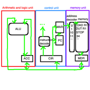
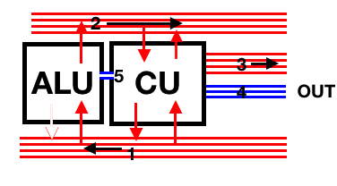
Rounded squares are components, squares are registers. Light-green arrows are busses
The instruction ready is the lower assembly language, so we want to integrate that more with the hardware side. This revolves around the fetch-decode-execute cycle (explained above). In the CPU, at that place will be 4 important registers,
the Programme Counter (PC), keeps rail of which plan the computer is currently on
the Memory Address Register (MAR), keeps rails of where the adjacent memory location will be
the Retentiveness Data Register (MDR), keeps track of what the memory AT the location is
the Current Instruction Register (CIR), keeps rail of what didactics is currently being worked on
and the ALU Accumulator (ACC), keeps track of the input and output from the ALU
In that location are as well four components to go on in mind, the Accost Decoder, the retentivity, the Instruction Decoder and the ALU.
FETCH The program will get the next didactics.
- PC sends the instruction number to the MAR
- PC increments by 1, to prepare for the side by side instruction
- Address Decoder decodes the accost, and requests information at that address from the retention
- MDR receives the requested data (in the instance of the motion-picture show, if the MAR is 0001, information technology receives 'LOADR1 1')
DECODE The program will identify what the instruction is
- CIR receives the information from the MDR, through the data menstruum
- Instruction Decoder decodes the instruction and what to practise
EXECUTE The program volition execute the instruction
- In the case of the picture, the program receives 'LOADR1 ane' as the teaching, the Instruction Decoder splits the instruction up into the opcode and the operand.
The opcode is 'LOADR1' and the operand is 'ane'.
- Operand is sent to the MAR, to get the information at that accost
- MDR receives the information at that address (in the example, it is the same line)
Now 4 things could happen depending on what the pedagogy is.
If the instruction is an Add instruction, the ACC will be told to receive the information from the information menstruation and the ALU volition perform operations on it, outputting it to the ACC again.
If the educational activity is a LOAD education, the CU volition load the pedagogy to the annals.
If the instruction is a STORE education, the CU will instead Ready the data at the location specified past the MAR in the memory.
If the instruction is an OUT instruction, the CU will send the instruction to the output peripheral.
REPEAT The instruction cycle repeats itself until it reaches a Finish teaching or runs out of memory
Step 3: Instruction set and machine architecture (PRACTICE) [ ]
Affiliate 2: Planning a Redstone Reckoner [ ]
A redstone computer can be planned very much similar a real computer, post-obit principles used in computer design and hardware architecture. There are several central design decisions that will affect the system; the size and performance of your prospective reckoner should exist fabricated concretely prior to the construction of specific components.
Building a redstone computer volition require an agreement of these five concepts and consider the most suitable approach, which would be about practical for your estimator.
- Motorcar-Architecture (Components of a figurer, what are they and what they do)
- Execution Model (The organization of components, making them efficient)
- Give-and-take Size (How many bits the organisation uses. Usually, powers of 2, around 4, 8, 16 flake is normal in Minecraft)
- Instruction Prepare (The instructions to be performed past the CPU)
and nosotros will be applying this knowledge and plan the architecture of our CPU in the concluding section. This CPU will and so be built in the adjacent chapter.
Fundamentals of a Calculator [ ]
A computer is a machine which has the power to
- Read and write from a memory which tin can be addressed
- Perform comparisons on the state of the memory, and perform an functioning every bit a upshot of that. These operations include rewriting retention.
- Start functions based on content written in the memory. We call such content "programs + data", and the act of writing them programming.
A very notable example of this is the most basic concept of computing, a Turing machine, where the car will read from one infinite line of code and instruction set in order to consummate a office.
Designing and building a Turing machine in Minecraft is possible. This even so, is not covered as we will be designing something more basic.
Auto-Compages [ ]
There are 5 fundamental components in a basic modern figurer. These are essential in order to produce a performance computer and manipulate data by performing computations.

five components of a reckoner
Arithmetic Logic Unit (ALU) (optional, but is normally present)
- Perform adding and subtracting
- Compare booleans using logic gates
Control Unit of measurement (CU)
- Perform/Execute instructions sent to it
- Communicate with all components
Data Retentivity
- Store and return data from memory
Instruction Retentiveness
- Return instructions, sent to the CU
- Can be set up, but doesn't demand to exist every bit often as the Data Memory
Input/Output devices (I/O)
- Allows the computer to communicate with the world and the actor.
- Can input information the estimator (button button, daylight sensor)
- Tin output information from the computer (redstone lamp, notation block)
Calculator Data Storage [ ]
At that place are many methods of storing data, in Minecraft or in real life. The states of memory usually are binary, either on or off and tin be computed with boolean logic.
On a computer, there are three types of storage. Keeping in mind that increasing the device's capacity would increase its size, each type would have speed and capacity advisable to it.
Main Storage [ ]
These are the storage which direct accessible to the CPU, referred to as memory and is fastest to access only normally is smaller in capacity for information technology to be addressed quicker.
Registers & Flags [ ]
Fastest is the memory stored within the CPU. These are registers and flags equally they can be fix almost instantaneously and do not require any address sent to it as there is simply one byte stored in each register. Redstone $.25 that tin be toggled are extremely big but tin exist toggled within 2 ticks. This requires a very large amount of space just is perfect for caches and registers. The redstone is likewise required for logic gates (non shown) to set up the flake, as in the images, sending an input would cause the chip to flip. The gate would take up more than space. Registers could too utilize locking redstone repeaters and timing them correctly. This is explained beneath, in RAM). With the utilise of a computer clock, information technology may not exist necessary to build registers. Registers are useful when the data goes through the line earlier either the CU or ALU is ready to process it. It would save it to the register and wait until the CU or ALU can perform its function.
Caches [ ]
2d to those are caches, which feed information into the processor. In existent life, they are separated into levels, each one with separate speed and capacities. It is useful for the same reason as the registers.
Random Access Retentivity (RAM) [ ]
Thirdly is Random Admission Memory (RAM), this is much slower than the caches and registers as they accept address systems. They are connected to iii busses, data bus, command bus and the address bus. The data is sent through the data bus, either setting the RAM or getting values from the RAM. The control passenger vehicle tells it whether it is being get or set. The address jitney tells the RAM where the byte is. Refer to the Architecture of the Computer to understand this more in-depth. RAM is very useful and could fully replace tertiary memory (explained below) because of its non-volatility in Minecraft. Volatile ways that when power is lost, it will lose information. The RAM will non lose information different in real life, and therefore in an excellent method of storing information.
The RAM in the first case is utilizing the locking redstone repeaters with the correct timing. This requires a bit of a plan merely is very space-efficient. The conversion of a bus to the lines in order to lock the redstone repeaters as well requires setting timings. This is fourth dimension-consuming, much more than than the registers, however, information technology is very meaty and efficient. The address double-decker (greenish) would turn in binary to unlock a certain byte, either to be read or set by the control bus (second line, on the left).
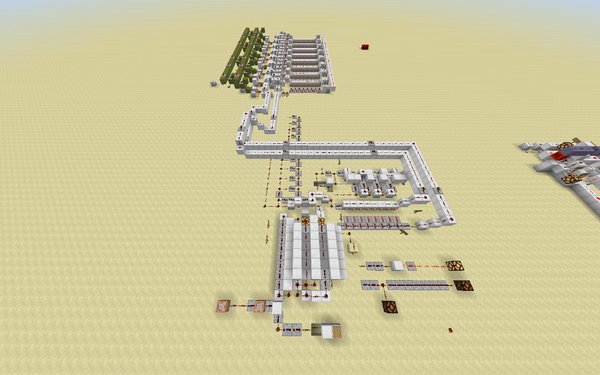
Near often, making it volatile has no use in Minecraft, so the easiest way to brand some is to use d-flip-flops and to add a reading and writing function. The bottom image shows instead of locking repeaters, it uses d-flip-flops which is much more than space inefficient but simpler to build. D-flip-flops work more or less similar locked repeaters, one input - if on, unlocks in until the input is off and the other will fix it once unlocked. The output can be read as a bit and with a NAND gate, be ignored or put onto the bus. This is gone over in particular in the 2d chapter, Tutorial on building a Reckoner. Alibi the texture pack.
Random Admission Retentivity as well known as RAM is a kind of memory used by programs and is volatile. Volatile means that when the power is lost, it will lose information. Most oftentimes, making it volatile has no utilise in Minecraft, so the easiest way to make some is to use d-flip-flops and to add a reading and writing part.
Secondary Storage [ ]
These are equivalent of HDDs and SSDs. There is a very compact storage technique, involving redstone comparators with the power to store up to 1KB, existence practically sized.
Third Storage [ ]
3rd and last, is a 3rd memory, which requires a lot of time to read/write but can hold massive amounts of information at the expense of speed. Real-earth tertiary storage use a mechanism of mounting the memory which takes near a minute for each bulldoze. This is used for archival purposes and for memory which is rarely used. In Minecraft, a system where shulker boxes are used and block in the shulker boxes must be sorted out by a sorting arrangement to represent a form of data. This can too exist used to create removable storage. The read/write speed is adequately wearisome due to the massive corporeality of comparators and a lot of time is required. The aforementioned mods could speed upward tick rate and eliminate this trouble, however. This is used for storing long-term data that needed to be loaded at the beginning of a plan or rarely due to its poor read/write speed and large capacity. This is the equivalent of a real computer'southward hard deejay or solid-land bulldoze.
Execution Model [ ]
The technique of storing blocks of instructions called programs within memory is what allows computers to perform such a variety of tasks.
The apparatus employed by a computer for storing and retrieving these programs is the computer's Execution Model.
Two of the globe's virtually successful execution models, Harvard and von Neumann, run on nearly 100% of the computers bachelor today.
This is more than advanced, and is for inquisitive and curious readers
Harvard [ ]
The Harvard architecture physically separates the apparatus for retrieving the instructions which make up an active program from that of the data admission apparatus which the program accesses during execution.
Programs written for computers employing a Harvard architecture may perform upwards-to 100% faster for tasks that access the main memory passenger vehicle. Notation notwithstanding that sure memory circuitry is necessarily larger for those who select a Harvard architecture. Harvard architecture is very important.
von Neumann [ ]
The von Neumann architecture uses a two-pace process to execute instructions. First, the memory containing the side by side instruction is loaded, then the new instruction just loaded is immune to access this same retentiveness as it executes; using a unmarried memory for both plan and data facilitates Meta-Programming engineering science like compilers and Self-modifying Code.
The von Neumann compages was the starting time proposed model of computation and almost all existent-world computers are von Neumann in nature.
Word sizes [ ]
Word-size is a principal gene in a figurer's physical size.
In Minecraft, machines from 1-bit all the way up to 32-$.25 have been successfully constructed.
Mutual discussion-size combinations:
| Data | Instruction |
|---|---|
| iv | 8 |
| 8 | eight |
| 8 | sixteen |
| sixteen | 16 |
Information-Word [ ]
The amount of information a computer can manipulate at any item time is representative of the computer's data discussion-size.
In digital binary, the computer's data-discussion size (measured in $.25) is equal to the width or number of channels in the computer's main bus.
Data-Words commonly represent integers or whole numbers encoded every bit patterns of binary digits.
The maximum sized number representable past a Binary encoded integer is given by 2data-word width in bits - 1.
For example, a computer with a data-word size of 8-flake will have eight channels on its bus (fix of wires, connecting components) and therefore, nosotros can count up to (28 - 1). 255. Counting further than 255 is not possible with viii bits, equally the functioning 255 + 1 carries over a one, which requires a ninth bit or what is chosen a binary overflow volition occur, returning 0 every bit the answer, which is incorrect.
This is simply visualized;
| 1 | 1 | i | one | 1 | 1 | one | 1 | 255 | |
| + | 0 | 0 | 0 | 0 | 0 | 0 | 0 | 1 | one |
| = | 0 | 0 | 0 | 0 | 0 | 0 | 0 | 0 | 0 |
Some common Integer information sizes are:
| Max Representable Number | Number of $.25 Required |
|---|---|
| 1 = (21 - 1) | one |
| 7 = (23 - one) | 3 |
| xv = (24 - 1) | 4 |
| 255 = (ii8 - 1) | 8 |
| 65535 = (216 - i) | 16 |
| 4294967295 = (232 - ane) | 32 |
Information-Give-and-take size besides governs the maximum size of numbers which can be processed by a computer'due south ALU (Arithmetic and Logic Unit).
Education-Discussion [ ]
The amount of data a computer needs in gild to complete one unmarried education is representative of a reckoner's teaching give-and-take-size.
The teaching-give-and-take size of a computer is more often than not a multiple of its Information-Discussion size, This helps minimize retention misalignment while retrieving instructions during plan execution.
Teaching Set [ ]
This is a collection of instructions the control unit (CU) tin can decode, and so execute.
Instructions are essentially functions run by the calculator, examples of instructions include:
- Add, subtract, multiply and divide
- Read/Write from RAM/ROM/tertiary retention
- Load and unload data into the RAM
- Branching to other parts of the code
- Comparison registers
- Selecting a logic function (NAND, NOR, Non etc.)
Instructions tin exist programmed into the RAM, loaded from ROM or straight activated by using a lever or button. Each instruction would have its own specific binary string assigned to information technology (due east.thousand. 0000=Load data from register 0001=add A and B 1011=Save RAM into third retentiveness etc.) and would probably crave its ain binary to decimal or binary to BCD to decimal encoders and buses to the ALU/registers.
Architecture of the Computer [ ]
Inside the reckoner, there is a Central Processing Unit (not to be confused with the Command Unit (CU), a component inside the CPU), which in real life, is a very small and powerful component that acts as more than or less, the brain of the computer. In Minecraft, it is difficult to compact it to the calibration we see in existent life so don't worry if information technology looks incorrect.
We will first exist designing our 4-bit Key Processing Unit of measurement in the next affiliate, equally information technology is the about important thing in our figurer with the Execution Model (the method of communication and organization of the CPU) in mind, (talked about in this folio, before, in the Execution Model section) we can map out the construction of the computer.
Map of the CPU, based on the Havard Execution Manner
The CPU follows a cycle four steps, fetch, decode, execute and (sometimes) stores to perform instructions. The CPU showtime fetches the instruction from RAM, decodes what it means (the teaching volition most likely be a number, and the CPU must find out what number it is), and once it understands what the pedagogy is, it will perform that action. This sometimes requires the data to be put back into the storage, therefore it will shop the information. The cycle is then repeated.
Busses [ ]
There are 5 busses in the CPU, each to conduct information from one component to the adjacent. Busses are channels of redstone connecting each component. Since nosotros are building a four-scrap computer, we just need iv channels in our bus. These are the ruby-red and blue lines connecting the components inside the CPU. Discover that the blue buses take less than iv lines, this is considering they do non carry data. Since busses tin can only carry information one style (in Minecraft, due to repeaters simply working one way), there are 2 buses connecting the CPU to the outer reckoner.
The get-go autobus is the data autobus, this is to transfer information from the storage or I/O devices to the CU. Instructions are likewise sent through this line The CU tin can likewise use this coach to transfer information to the ALU. The ALU cannot transfer data onto this bus considering buses only work one way and once the data is taken past the ALU, the bus cuts off beyond the ALU. Data from the ALU is passed through bus 2.
The second motorcoach is the data bus, just returns the data from the ALU to the CU. The CU cannot send information through this motorbus to the ALU because the motorcoach goes from left to correct and works in one direction only. The CU tin can transport information dorsum to the storage units though, and is used to ready values of storage devices.
The tertiary passenger vehicle is the address bus, which the CU can send the address of storage. This is where the data resides. For example, the CU asks for the accost of the byte living in 0001. It sends the address (0001) through the address bus and the RAM will render the value of the byte through the first jitney. 0001 is the location of the byte, not the value of it.
The quaternary autobus is the control bus, which the CU volition communicate with the RAM with. For example, ane wire could tell the RAM to set the byte to the value to the information sent to it by the CU. Another wire could tell the RAM to get the byte from the accost sent to it by the CU.
The 5th bus is another control motorcoach, linking with the ALU, which sends flags from the ALU. Flags are notes which could be error messages. For case, the CU could ask the ALU to add fifteen and i in a 4-bit organisation. Calculation 15 and 1 in four bits would yield 0 (explained above) and this is chosen a binary overflow. This is an error and the ALU will tell the CU about this through the fifth bus equally a flag. The CPU could also send data to the ALU and ask for it to perform an activity with that information.
Components [ ]
Command Unit (CU) will fetch instructions from the instruction ROM (for other computers, instructions tin be changed and therefore is RAM. For our example, we are running a fixed programme and do not need to change the instructions. This simplifies the process entirely and the didactics is Read-Just Retentivity (ROM)). Within the CU, it will so decode the instruction, which is commonly a number, into a sensible action. It volition then perform that activeness and if the instruction requires, store the issue into the RAM. Information technology communicates with the RAM through the control coach and receives flags from the ALU. It tin also ask the ALU to perform deportment on data it sends to the ALU (eastward.thou. improver). To communicate with the RAM, for example, one wire could tell the RAM to set the byte (the location of it is specified through the third, address bus) to the value to the data sent to it by the CU through the second, data double-decker.
Arithmetic logic unit (ALU) will execute instructions sent to it from the CU and will compare binary numbers and communicate with the Command Unit. It can do simple add-on and subtraction which can be repeated to practise multiplication and whole-number partitioning, outputting a whole number (and then division). At that place are too logic gates for booleans, the fundamental logic gates are required, such as the NOT gate and the NAND gate.
Now we can choose from a range of designs of busses, each contributing to the aforementioned three central designing goals of a Minecraft computer.
Tips [ ]
- The histrion may want to utilise mods or data packs like WorldEdit.
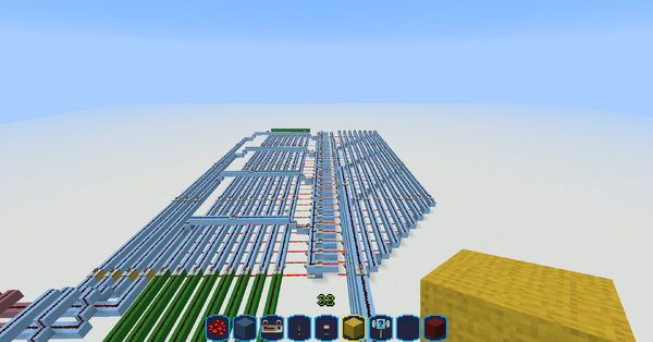
- Color code your computer (apply blue wool or concrete for RAM, xanthous for the ALU, etc.)
- First small, and get the hang of modest computers before you try more complex machines.
- Construction blocks can be very helpful for moving components around, and combining multiple components together. However, notation that these cannot be obtained without using commands.
See also [ ]
- Redstone
- Redstone circuit
- Redstone clock
- Logic circuit
- Memory circuit
- Pulse excursion
- Transmission circuit
- Tutorials/Advanced redstone circuits
- Tutorials/Computer
- Tutorials/Press
- Tutorials/Telegraph
References [ ]
- ↑ Signed number representations in Wikipedia

How To Make A Computer In Minecraft,
Source: https://minecraft.fandom.com/wiki/Tutorials/Redstone_computers
Posted by: perezmonal1977.blogspot.com
0 Response to "How To Make A Computer In Minecraft"
Post a Comment